
Basic Knowledge of Industrial Valves
Valves are the core control components of industrial fluid pipeline systems. They are widely used in water treatment, chemical industry, oil & gas, municipal engineering, metallurgy, power generation and other industries, performing functions such as medium shut-off, opening, flow regulation, backflow prevention and safety pressure relief. Incorrect valve selection may lead to leakage, equipment damage, system shutdown and even safety accidents. This paper systematically introduces the types of industrial valves, model interpretation, basic structure, material selection, actuators and frequently asked questions, providing scientific references for project selection, procurement and technical evaluation.Zhejiang Bolaisi Valve Co., Ltd. has a professional sales and technical team, capable of providing you with accurate selection recommendations.
Table of Contents
I. Main Types, Functional Features and Distinction of Industrial Valves
II. Full Interpretation of National Standard Valve Model (JB/T308-2004)
III. Basic Structure of Valve and Functions of Each Component
IV. Functions, Classification and Application Scenarios of Actuators
V.FAQ - Frequently Asked Questions
I. Main Types, Functional Features and Distinction of Industrial Valves
According to functions and applications, industrial valves can be divided into shut-off & regulating valves, check & protection valves, safety pressure relief valves, and special-purpose valves.
1. Shut-off and Regulating Valves
| Valve Type | Core Function | Advantages | Applicable Working Conditions |
| Gate Valve | Full shut-off or full opening of pipeline; not suitable for flow regulation | Extremely low flow resistance, bidirectional flow, good sealing performance; available in rising stem and non-rising stem designs | Water supply & drainage, steam, oil trunk pipelines. Rising stem type for open/closed status visual check. Soft-seated gate valves mostly for sewage and water supply. Hard-seated gate valves for high-temperature steam service. |
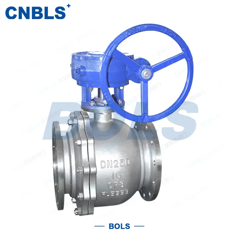
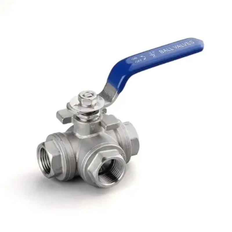
| Ball Valve | Quick on-off by 90° rotation, full bore with low flow resistance | Fast operation, excellent sealing; two designs: floating ball and trunnion mounted ball | Corrosive media in chemical industry, oil & gas, water treatment, frequent cycling service. T/L type 3-way ball valves for medium flow direction switching. |
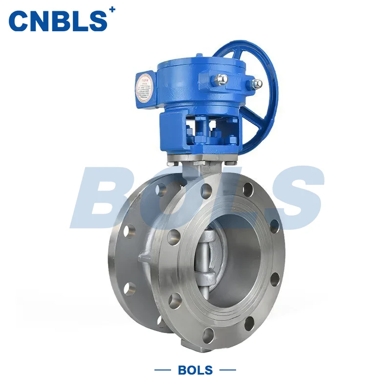
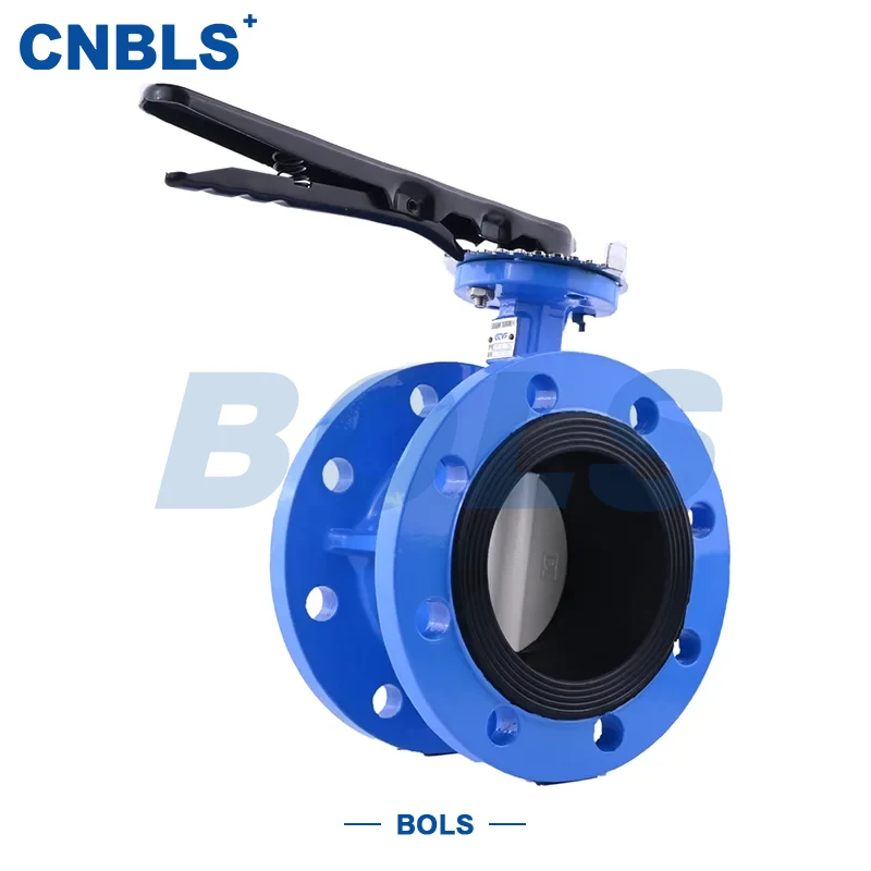
| Butterfly Valve | Shut-off or rough flow regulation; outstanding advantage for large sizes | Compact and lightweight, small installation space, cost-effective for large diameters | Municipal water supply & drainage, circulating water, ventilation and flue gas. Soft-seated for ambient temperature; hard-seated for high-temperature flue gas. |
| Globe Valve | Shut-off + flow regulation; fixed flow direction (flow under the disc) | Good regulation accuracy, reliable sealing, easy maintenance | Steam, instrument pipelines, sampling systems, clean medium pipelines requiring flow regulation. |
| Knife Gate Valve | Shut-off for media containing particles and slurry | Straight bore without dead space, less material accumulation; suitable for mud, sewage and corrosive slurry | Sewage treatment, mine slurry, chemical corrosive media, large diameter slurry pipelines. |
2. Check Valves (Unidirectional protection, prevents medium backflow, no external actuation required)
They open and close automatically relying on the medium’s own pressure.
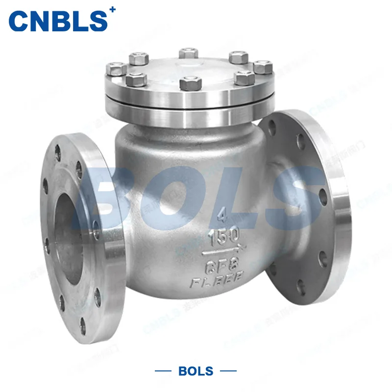
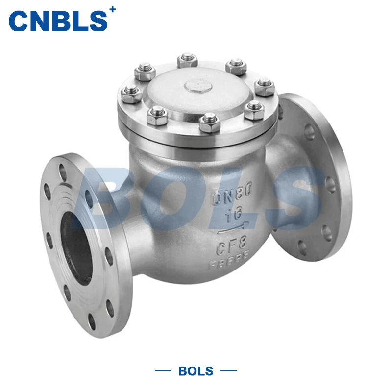
· Swing Check Valve: The disc swings around a hinge pin, with moderate flow resistance, suitable for large bore sizes.
· Lift Check Valve: The disc moves vertically up and down, featuring better sealing but relatively high flow resistance.
· Vertical Check Valve: Designed specifically for vertically mounted pipelines.
Typical application: Pump outlet, to prevent medium backflow upon shutdown and protect pump equipment from damage.
3. Regulating Valves
Throttle valves and control valves: adjust the opening of the valve plug to precisely control pipeline flow rate and pressure, mostly used for parameter regulation of process systems.
4. Safety Protection Valves· Safety Valve: Automatically relieves pressure when the system overpressurizes, protecting pressure vessels and pipelines.
· Pressure Reducing Valve: Reduces high upstream pressure and stabilizes the outlet pressure downstream.
· Steam Trap: Drains condensate from steam systems while preventing steam leakage to save energy.
II. Full Interpretation of National Standard Valve Model (JB/T308-2004)
Model Coding Sequence
Type Code + Actuator Code + Connection Type Code + Structure Type Code + Seat Surface Code + Nominal Pressure + Body Material Code
1. Type Code (1st Letter):
| Valve Type | Code | Valve Type | Code |
| Spring Loaded Safety Valve | A | Blowdown Valve | P |
| Butterfly Valve | D | Ball Valve | Q |
| Diaphragm Valve | G | Steam Trap | S |
| Lever Safety Valve | GA | Plunger Valve | U |
| Check Valve and Foot Valve | H | Plug Valve | X |
| Globe Valve | J | Pressure Reducing Valve | Y |
| Throttle Valve | L | Gate Valve | Z |
2. Actuator Code (Numeral; omitted for manual operation)
| Actuation Type | Code | Actuation Type | Code |
| Solenoid Actuated | 0 | Bevel Gear | 5 |
| Solenoid-Hydraulic | 1 | Pneumatic | 6 |
| Electro-Hydraulic | 2 | Hydraulic | 7 |
| Worm Gear | 3 | Pneumatic-Hydraulic | 8 |
| Spur Gear | 4 | Electric | 9 |
3. Connection Type Code
| Connection Type | Code | Connection Type | Code |
| Internal Thread | 1 | Wafer | 7 |
| External Thread | 2 | Clamp | 8 |
| Flanged | 4 | Ferrule | 9 |
| Welded | 6 | — | — |
4. Structure Type Code
Gate Valve (Z)
| Structure Type | Code | |||
| Rising Stem | Wedge Gate | Elastic Wedge | 0 | |
| Rigid Wedge | Single Wedge | 1 | ||
| Double Wedge | 2 | |||
| Parallel Gate | Single Wedge | 3 | ||
| Double Wedge | 4 | |||
| Non-Rising Stem(NRS) | Wedge Gate | Single Wedge | 5 | |
| Double Wedge | 6 | |||
| Parallel Gate | Single Wedge | 7 | ||
| Double Wedge | 8 | |||
Globe Valve (J)、Throttle Valve (L)、Plunger Valve (U)
| Structure Type | Code | Structure Type | Code | ||
| Unbalanced Disc | Straight Through Passage | 1 | Balanced Disc | Straight through passage | 6 |
| Z-type Passage | 2 | Angle passage | 7 | ||
| Three-way Passage | 3 | - | - | ||
| Angle Passage | 4 | - | - | ||
| Straight Flow Passage | 5 | - | - | ||
Ball Valve (Q)
| Structure Type | Code | Structure Type | Code | ||
| Floating Ball | Straight Through Passage | 1 | Trunnion Ball | Straight Through Passage | 7 |
| Y-type Three-way Passage | 2 | Four-way Passage | 6 | ||
| L-type Three-way Passage | 4 | L-type Three-way Passage | 8 | ||
| T-type Three-way Passage | 5 | T-type Three-way Passage | 9 | ||
| - | - | Semi-ball Straight Through | 0 | ||
Butterfly Valve (D)
| Structure Type | Code | Structure Type | Code | ||
| Sealing Type | Single Offset | 0 | Non-sealing Type | Single Offset | 5 |
| Concentric Disc | 1 | Concentric Disc | 6 | ||
| Double Offset | 2 | Double Offset | 7 | ||
| Triple Offset | 3 | Triple Offset | 8 | ||
| Linkage Mechanism | 4 | Linkage Mechanism | 9 | ||
Diaphragm Valve (G)
| Structure Type | Code | Structure Type | Code |
| Weir-type Passage | 1 | Straight Through Passage | 6 |
| Straight Flow Passage | 5 | Y-angle Passage | 8 |
Plug Valve (X)
| Structure Type | Code | Structure Type | Code | ||
| Gland Packing Seal | Straight Through Passage | 3 | Oil Seal | Straight Through Passage | 7 |
| T-type Three-way Passage | 4 | T-type Three-way Passage | 8 | ||
| Four-way Passage | 5 | - | - | ||
Check Valve (H)
| Structure Type | Code | Structure Type | Code | ||
| Lift Disc | Straight Through Passage | 1 | Swing Disc | Single Disc Structure | 4 |
| Vertical Type | 2 | Multi-disc Structure | 5 | ||
| Angle Passage | 3 | Double Disc Structure | 6 | ||
| - | - | - | Butterfly Check Type | 7 | |
Safety Valve (A)
| Structure Type | Code | Structure Type | Code | ||
| Spring Loaded, Spring Enclosed Type | Full Lift Type with Radiator | 0 | Spring Loaded, Spring Unenclosed with Wrench | Low Lift Type Duplex Valve | 3 |
| Low Lift Type | 1 | Low Lift Type | 7 | ||
| Full Lift Type | 2 | Full Lift Type | 8 | ||
| Full Lift Type with Wrench | 4 | - | |||
| Lever Type | Single Lever | 2 | Full Lift Type with Control Mechanism | - | 6 |
| Double Lever | 4 | Pilot Operated Type | - | 9 | |
Pressure Reducing Valve (Y)
| Structure Type | Code | Structure Type | Code |
| Diaphragm Type | 1 | Bellows Type | 4 |
| Spring Diaphragm Type | 2 | Lever Type | 5 |
| Piston Type | 3 | — | — |
Steam Trap (S)
| Structure Type | Code | Structure Type | Code |
| Ball Float Type | 1 | Steam Pressure / Bellows Type | 6 |
| Bucket Float Type | 3 | Bimetallic Type | 7 |
| Liquid / Solid Expansion Type | 4 | Pilot Type | 8 |
| Inverted Bucket Type | 5 | Disc Thermodynamic Type | 9 |
Blowdown Valve (P)
| Structure Type | Code | Structure Type | Code | ||
| Liquid Level Connection Drain | Globe Straight Type | 1 | Intermittent Bottom Drain | Globe Straight Type | 5 |
| Globe Angle Type | 2 | Globe Straight Type | 6 | ||
| - | - | Globe Angle Type | 7 | ||
| - | - | Straight Type with Floating Gate Disc | 8 | ||
5.Sealing Face / Lining Material Code
| Sealing face or lining material | Code | Sealing face or lining material | Code |
| Tin Babbitt Alloy | B | Nylon Plastic | N |
| Enamel | C | Boronized Steel | P |
| Nitrided Steel | D | Lead Lining | Q |
| Fluoroplastic | F | Austenitic Stainless Steel | R |
| Ceramic | G | Plastic | S |
| Cr13 Stainless Steel | H | Copper Alloy | T |
| Rubber Lining | J | Rubber | X |
| Monel Alloy | M | Hard Alloy | Y |
6.Nominal Pressure PN10、PN16、PN25、PN40、PN64、PN100
7.Body Material Code
| Body Material | Code | Body Material | Code |
| Carbon Steel | C | Cr-Ni-Mo Stainless Steel | R |
| Cr13 Stainless Steel | H | Plastic | S |
| Cr-Mo Steel | I | Copper and Copper Alloy | T |
| Malleable Cast Iron | K | Titanium and Titanium Alloy | Ti |
| Aluminum Alloy | L | Cr-Mo-V Steel | V |
| Cr-Ni Stainless Steel | P | Grey Cast Iron | Z |
| Ductile Iron | Q | — | — |
| Note: Material grades such as CF3, CF8, CF3M, CF8M may be marked directly on the valve body. | |||
III. Basic Structure of Valve and Functions of Each Component
Most industrial valves are mainly composed of six core parts: valve body, bonnet, closure member (gate / ball / disc / clapper), stem, sealing assembly and transmission component.
1.Valve Body: The main shell of the valve. It bears the pressure of the medium and accommodates all internal parts. As the core pressure-bearing component, the material of the valve body determines the valve’s resistance to temperature, pressure and corrosion.
2.Bonnet: Sealing cover on the top of the valve body, used for mounting the stem and packing. It is removable for easy maintenance of internal parts.
3.Closure Member: The core part that performs opening and closing operations. It includes gate (gate valve), ball (ball valve), disc (butterfly valve), clapper (globe valve, check valve), which directly contacts the medium to cut off or connect the flow path.
4.Stem: Transmits torque to transfer power from the handwheel / actuator to the closure member. For rising stem valves, the stem extends out during opening and closing, allowing direct visual check of valve status. For non-rising stem valves, the stem does not extend, saving installation height.
5.Sealing System
Seat Seal: Located between the closure member and valve seat, it cuts off the pipeline medium. Divided into soft seal (rubber, PTFE) and hard seal (metal overlay welding).
Packing Seal: Applied at the gap between stem and bonnet to prevent medium leakage outward along the stem. Graphite and PTFE packing are commonly used.
Soft Seal VS Hard Seal Distinction
· Soft Seal: Sealing materials are rubber and PTFE. Good shut-off leakage class, suitable for ambient temperature. EPDM: -20~+120℃; PTFE: -20~150℃. Not suitable for high temperature and particle erosion.
· Hard Seal: Metal-to-metal seal. High temperature and high pressure resistance, wear-resistant. Zero-leakage performance is inferior to soft seal.
6.Transmission Components: Handwheel, gear box, worm gear. They reduce operating torque. Gear reduction is mandatory for large bore valves.
IV. Functions, Classification and Application Scenarios of Actuators
The actuator provides power for valve opening and closing. It is divided into five categories: manual, worm gear, electric, pneumatic and hydraulic.
1.Manual Actuation (Handwheel / Lever)
Function: Direct manual operation. Large bore valves are equipped with worm gear boxes to reduce operating torque.
Application: Small DN size valves, low opening & closing frequency, local on-site operation without automation requirements.
2.Worm Gear / Gearbox Actuation
Function: It is a manual speed reduction mechanism to amplify manual torque, essential for large bore valves.
Application: Knife gate valves and gate valves of DN200, DN300, DN400, no automation requirement.
3.Electric Actuator (Electric Drive)
Function: The motor drives valve opening and closing. Remote automatic control can be realized, and some are equipped with position signal feedback. Power supply includes 220V single-phase and 380V three-phase.
Application: Water treatment, factory automation pipelines requiring remote monitoring. Explosion-proof electric actuators are selected for explosion hazardous areas.
4.Pneumatic Actuator
Function: Driven by compressed air. It features fast opening and closing speed, inherently no electric spark with excellent explosion-proof performance. Available in single-acting and double-acting types.
Application: Flammable and explosive working conditions in chemical industry, frequent on-off operations. Compressed air supply must be provided on site.
5.Hydraulic Actuator
Function: Driven by hydraulic oil with huge output torque.
Application: Extra large bore, high pressure and heavy-duty valves. High equipment cost, a hydraulic power unit is required.
Summary for Selection:
Manual operation and low frequency → Handwheel / Gearbox;
Remote automation with sufficient power supply → Electric actuator;
Explosion-proof chemical service, frequent operation and available compressed air on site → Pneumatic actuator;
Extra large bore, high pressure and heavy duty → Hydraulic actuator.
Zhejiang Bolaisi Valve Co., Ltd. offers a wide range of products with complete specifications, making valve selection straightforward.
V.FAQ - Frequently Asked Questions
Q1: Can soft seal gate valves be used for steam service?
A: Ordinary EPDM rubber soft seal can withstand temperatures up to approximately 80~120℃. It cannot be used for high-temperature steam. Metal hard seal gate valves are recommended for steam working conditions.
Q2: How to choose between CF8 and CF3M?
A: Select CF8 (304) for medium such as ordinary water and food service. CF3M (316L) must be selected if the medium contains chloride ions, seawater, weak acid and weak alkali corrosive media. Molybdenum element improves resistance to pitting corrosion.
Q3: Can gate valves be used for flow regulation?
A: Not recommended. Gate valves are designed for fully open and fully closed service. In the half-open position, the medium flows at high velocity and erodes the sealing surface of the gate, which will quickly cause seal wear and permanent leakage. Globe valves or control valves are preferred for flow regulation.
Q4: What is the difference between rising stem gate valve and non-rising stem gate valve?
A: Rising stem: The stem extends outward during opening and closing, so the valve status can be checked visually. It requires larger installation height. Non-rising stem: The stem does not extend, the overall height remains unchanged. Suitable for limited installation space, but the open/closed status cannot be judged visually from outside; a position indicator must be equipped.
Q5: What is the difference between wafer type valve and flanged valve?
A: Flanged valve comes with integral flanges, two flanges are connected by bolts. Wafer valve has no flanges itself; the valve body is clamped between two pipeline flanges. Wafer valves feature light weight and lower cost, but the pressure rating is relatively limited.
Q6: Is 380V power supply mandatory for electric valves?
A: Small bore actuators are available in 220V single-phase. High-torque large bore actuators generally adopt 380V three-phase power supply. The voltage specification must be clearly specified when placing orders.
Q7: Are knife gate valves suitable for long-term service in clean water pipelines?
A: The structure of knife gate valves is designed for slurry with particles. Gate valves are preferred for clean water service without particles. The sealing life of knife gate valves is inferior to that of gate valves.
Q8: What does PN16 mean?
A: PN stands for nominal pressure. PN16 equals 16 bar (1.6 MPa), which indicates the maximum allowable working pressure of the valve. Note: The pressure rating is related to the medium temperature. As temperature rises, the permissible actual working pressure decreases.
Conclusion
Valve selection is a systematic project. It is necessary to comprehensively consider medium, pH value, chloride ion content, temperature, nominal diameter DN, nominal pressure PN, connection type, actuation type, leakage class, installation space and explosion-proof requirements. If parameters are uncertain, please provide complete working conditions for valve model confirmation to avoid wrong selection.Choose Zhejiang Bolaisi Valve Co., Ltd., and you can purchase with confidence and use with peace of mind.
If you encounter difficulties in valve selection for your working conditions, you may contact Zhejiang Bolaisi Valve Co., Ltd. for technical support.
Next :
-
Related News
- How Does the Ball Valve Achieve Zero Leakage with Soft Seat Sealing Materials?
- What Makes Ball Valves the Preferred Choice for High-Pressure and High-Temperature Services?
- How does Ball Valve maintain tight sealing under high-temperature conditions?
- Why Is a Two Piece High Platform Flanged Ball Valve a Smart Choice for Modern Industrial Pipeline Control
- Why Are High Performance Ventilation Butterfly Valves Essential for Modern Industrial Airflow Control
- How Can a GB Flange Globe Valve Improve Industrial Pipeline Control and Operational Safety
Leave me a message
New Products